Listening To Satellites: A Journey With My RTL-SDR V3

NOTE: This is the log of my personal journey with satellite RF. If you’re looking for a tutorial, this might sound boring to you since it has many unnecessary details, and I’m not a professional. Have a look at the end of the post and the referred links.
For a long time (to be specific, from when I was 13), I was fascinated with radio signals and amateur radio hobbies, But you know, it’s difficult to practice such hobbies in Iran, where many of the needed components and parts are not available, or very expensive.
So I completely forgot my fascination with amateur radio, but it all changed when I got my hands on a new and unexpected gem, The “RTL-SDR Blog V3” dongle. I listened to all kinds of radio frequencies for days, but a new project caught my eye: Listening to satellites (or, more specifically, receiving their signal).
Which Satellites? Which Transmission Systems?
As you probably already know, there are a bunch of (well, more than a bunch, thanks to SpaceX) satellites orbiting above us. Many of them are now dead and space debris, but many of them are working (even partially. Some of the satellites have broken batteries and don’t work when orbiting the dark side of the Earth, but working when exposed to sunlight thanks to their solar panels). Most of these working satellites (if not all of them) communicate with their ground stations using radio waves (mostly transmitting data back to Earth).
The fun part of the story is, you can receive the signal of many of them; however, it’s probably useless to you because the data is encrypted. Luckily, some of these satellites are generous enough to send their data (or some of it) with no or weak encryption.
What data? It ranges from telemetry data about their batteries and internal systems to images from the Earth and even relayed data from other people (Some CubeSats and other satellites carry an amateur radio payload that receives the data transmitted to them on a specific frequency, and relays it back to the Earth on another frequency. This way, Satellite radio hobbyists can broadcast CW or audio and communicate with each other as the satellite passes above them).
These “data” are transmitted in various transmission systems. Older active American NOAA satellites transmit in APT and HRPT (and some more for different kinds of data), Russian Meteor-M 2 satellites transmit in LRPT and HRPT (most of them are now dead or malfunctioning, so no more LRPT from Meteor until Meteor-M 2–3), etc.
In this post, we will look into weather satellites like NOAA and METEOR and receive their live images from the Earth, some small CubeSats and their relayed and telemetry data, and finally, the legendary QO-100, a satellite in the GEO orbit that relays data to a wide area.
NOAA APT, The First Run
First, I tried the portable dipole antenna set that comes with the RTL-SDR package but had no success. So I went to a highway with a very open sight of the sky, opened the portable dipole antenna at 120 degrees, pointed it to the south, connected the dongle to my laptop, and opened SDR++. I tuned the SDR to 137.100 MHz and stared at the screen. Based on the n2yo calculation for my location, the satellite must be visible from my location right now, and a few seconds later, for the first time, I heard the amazing sound of the APT analog signals. I quickly started recording the signals in SDR++ and waited for the satellite pass to end. (Fun sidenote: I was holding the antenna with my hand, and people were staring at me like I was defusing a bomb; it was hilarious)
Now I had a WAV file containing the signals. To convert the analog signals to an image, There were two main options for me. First, it was the famous WXTOIMG, and the second option was noaa-apt. The first one was more advanced and had more options and outputs, but I was running Linux and didn’t need advanced options for now, so I used noaa-apt…
Looking from space at ourselves in real-time while a satellite passes above us?
It. was. beautiful.

First 137 MHz Antenna
Since I was VERY limited on hardware and tools, I quickly crafted a V Dipole antenna based on Adam 9A4QV design to get NOAA 15,18,19 satellite pictures. The design is very straightforward and poor-man-friendly.

You just need some coaxial cable, two aluminum/copper rods, a choc block, and something to mount the antenna on. It must have some distance from metal things, a suitable height from the floor (we’ll reach the calculation part later), and an open sight of the sky. Also, having an LNA will SIGNIFICANTLY improve your performance (If you use it right).
In my first design, I used two copper rods, fixed the antenna to a water pipe with some cable ties, and ignored the LNA.

After some trial and error, I installed the raspberry-NOAA-v2 on my RPI, connected the SDR dongle, and let it run. The result was lovely…

The above images were transmitted from NOAA 19 using the APT analog transmission system on ~137 MHz. These NOAA satellites also transmit higher-resolution images using the HRPT digital transmission system on a higher frequency. The high-resolution images are harder to receive and require a directional antenna, so let’s forget it for now.
As you can see, the original images are black and white, but you can add a “false color” to them.

METEOR-M2 LRPT
I had fun with NOAA satellites for a few days and then decided to get the METEOR-M2 LRPT signals which are also on ~137 MHz. Unlike the NOAA’s APT, LRPT signals are digital, so while NOAA’s APT transmits two channels with 4 km per pixel resolution, METEOR-M2 LRPT transmits three channels with 1 km per pixel, which results in a significantly better image.
The recording part is similar; however, the decoding is a bit more complex, so I let the raspberry-NOAA-v2 automate the whole process. You can also use SatDump.

Antenna Optimization
Despite getting the images successfully, they were far from perfect or even a good capture. u/PhaseRay suggested a radiation pattern issue with my antenna while I suspected the wirings.

He warned me about the height of the antenna. I didn’t have a clue that this was an important factor, so my knowledge was too short about how an antenna works. I started reading about it, and there were two options for my setup. First, to lower my antenna, and second to add a reflector to my setup, but I chose option 3: building a new antenna.
One of the most important steps in building an antenna is testing the antenna. There are various ways and methods to test an antenna, like testing with VNA or even simply with trial and error. Unfortunately, I was very limited in this step. Getting my hands on a VNA in Iran was very hard and expensive, and I even couldn't go with trial and error because there were just a few passes per day, and I had not any other reference signal in that frequency.
So I had only one option left, simulation. There is an old and popular antenna modeling system named NEC. It’s not easy to learn, but once you’ve learned it, you're saved.
I chose 4nec2 and started modeling my current V dipole antenna. It turned out that adding a reflector to my antenna at 80 cm from the ground would give me a pretty good antenna pattern in some directions. So, in theory, some of the passes (based on their path in the sky, from my point of view) will result in good captures.

So I fixed some wiring issues, added a reflector to the V dipole antenna, and waited a few days to see if I could capture such a pass, and it worked.

And as expected, this capture was just an exception because of its path, and at the same time, other passes with the same elevation were not good.

Before I move to the next part, let's have a look at how wiring and optimization are important:


The New Turnstile Antenna
With the help of the 4nec2 and the alicja.space design for their 435 MHz antenna, I calculated the numbers for the 137 MHz model and adopted the previous poor-man-friendly design to a turnstile to avoid 3d printing. Note that my version of the antenna is very dirty and worse than the original alicja.space design, just to simplify the process and use the same choc blocks and water pipe (yes, I'm very lazy).


The new turnstile antenna benefited from a wider antenna pattern, which helped me reduce the noise and nulls in the captures.
The results were beautiful, even without an LNA:

Later I added a Nooelec LaNA LNA, which I bought for double the price and waited three months for it to arrive; yes, having these things in Iran is challenging. (and I foolishly broke it recently)

The World of The Cubesats and 435 MHz
After three months, I decided it was time for Cubestats and telemetry data. So I modified my turnstile antenna for 435 MHz (the exact model of alicja.space).

Before seeing the results, let’s talk about Cubesats and 435 MHz. On 137 MHz, we had five or fewer satellites transmitting weather images. While it is impressive to look at satellite images above you, space satellites have much more to have fun with. Unlike the 137 MHz, there are dozens of satellites that transmit data on ~435 MHz, mostly Cubesats and mostly telemetry data (no more images, sad). So I didn’t have to wait until sunrise to test my setup. One hour after finishing the antenna, I got my first signal.
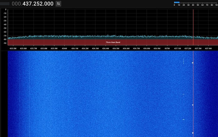
The small signal bursts in the above picture are digital frames that need to be decoded, but how?
SatNOGS Network, The Heaven of Amateur Ground Stations
Imagine a network of amateur radio hobbyists connected to observe the different satellites and share the data. Now make it all automatic (even better!), It’s SatNOGS.
SatNOGS offers open-source software and hardware for ground stations to make their station automatic and even connect to their network. They have a very good database of satellites and their status and transceivers.
They have a ready ISO image for RPI. You write it to an SD Card, connect your dongle to RPI, connect the RPI to the Internet, insert the token you generated from their website, and you’re done!
When you create a station in the SatNOGS network, you specify your antenna’s working bands and your station’s location. Then the network will automatically schedule the passes that your station will be able to receive and gets back the result from your station. You can look at some of the successful observations from the network.
I decided to use their system to automate things, but since the Iranian government is very strict in radio comms, connecting a ground station to a foreign network will have severe consequences. They simply won’t understand or care (which turned out to be right when they arrested me the last October because of researching Internet censorship); they will count it as spying.
Anyway, fortunately, the SatNOGS network itself is open source, so I launched a private instance on my home server and connected my RPI to it. It worked perfectly!
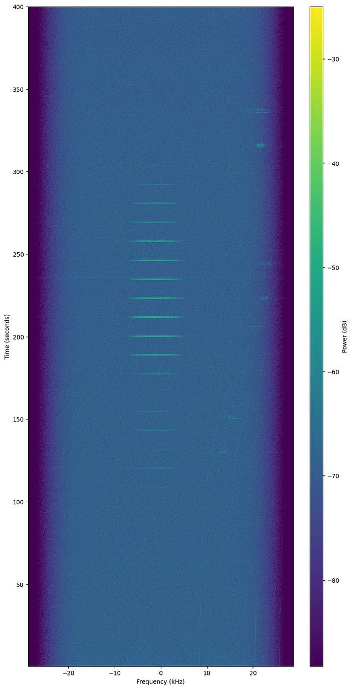


The above capture is some telemetry data from the GRIFEX satellite, which includes information like the satellite’s memory status, CPU status, Power status, etc.
SatNOGS also have a dashboard for satellites that have a public decoder for their telemetry. You can see the latest status of these satellites based on observations from the SatNOGS network worldwide.
Let’s Go GEO, QO-100 (Es’hail 2)
Until now, all of the discussed satellites were orbiting the LEO orbit, meaning their location relative to Earth constantly changes and moves. So you have to calculate when they will pass above you, their path, and their max elevation above the horizon. A higher elevation means a better pass.
But as you already know, there are satellites that are in the GEO orbit. Their location relative to Earth is constant, and we see them in a fixed position. In 2018, QO-100 provided the first amateur radio transponders in the GEO orbit, covering from Brazil to Thailand. QO-100 is VERY higher than LEO satellites like CubeSats (500 km VS 35000 km), and its downlinks are working in the X band, so obviously, no more omnidirectional antenna; we need a dish antenna.
Fortunately, since QO-100 is in the GEO orbit, we don’t need to move the antenna (unlike the higher bands for LEO satellites like NOAA HRPT, where you have to point a directional antenna at the moving satellite). We need a regular satellite dish and a custom LNB to receive the downlink.
QO-100 receives narrowband signals on 2400.050–2400.300 MHz and relays it back on 10489.550–10489.800 MHz (2401.500–2409.500 MHz and 10491.000–10499.000 MHz for wideband). Our LNB receives the downlink signal and downconverts it by 9750 MHz so we can get it on RTL-SDR.
For this satellite, I needed less crafting and more spending. I ordered a suitable LNB (also for double the price and with two months of waiting) and installed it on my LNB. Done! Oh wait, I forgot something…
LNBs need to be powered; this one needs 12–19V, so RTL-SDR V3’s 4.5V can’t power it on. Even worse, to switch the LNB’s polarization, you need to change the voltage. To inject power into the cable without destroying the signal or your dongle, you need to inject the power in one way and block the DC current in the other way (to the RTL-SDR). This power injector is named BIAS-TEE, and I forgot to buy one, and it was not available in Iran, and I had not the confidence to build one, but I had to.
It is a straightforward circuit. While blocking the DC from going to the RTL-SDR, it must allow the RF to pass.

So I read this post and created one with poor quality (RF circuits are very sensitive, so you have to handle them carefully, or you'll get no signal).


I powered the circuit, pointed the dish, and it worked!
You can listen to QO-100 online here.
The Conclusion
It was a very fun and educational project for me as a software guy. I send my regards to everyone who created content on this subject on the Internet, this project would be impossible without them. I might return to this project later and go for HRPT and HRIT. For now, I’m very satisfied with the results while having severe limitations in supplies and tools.
Softwares Used
SDR++: https://github.com/AlexandreRouma/SDRPlusPlus
WXTOIMG: https://www.rtl-sdr.com/tag/wxtoimg/
n2yo: https://www.n2yo.com/
noaa-apt: https://github.com/martinber/noaa-apt
raspberry-NOAA-v2: https://github.com/jekhokie/raspberry-noaa-v2
SatDump: https://github.com/SatDump/SatDump
4nec2: https://www.qsl.net/4nec2/
Custom Raspbian image with SatNOGS Client Ansible: https://wiki.satnogs.org/Raspberry_Pi#Download
satnogs-network: https://gitlab.com/librespacefoundation/satnogs/satnogs-network
Kaitai Web IDE: https://ide.kaitai.io/
Read More
RTL-SDR TUTORIAL: RECEIVING NOAA WEATHER SATELLITE IMAGES: https://www.rtl-sdr.com/rtl-sdr-tutorial-receiving-noaa-weather-satellite-images/
SIMPLE NOAA/METEOR WEATHER SATELLITE ANTENNA: A 137 MHZ V-DIPOLE: https://www.rtl-sdr.com/simple-noaameteor-weather-satellite-antenna-137-mhz-v-dipole/
How to build a turnstile antenna for 435Mhz (and connect it to SatNOGS network) — tutorial for beginners: https://alicja.space/blog/how-to-build-turnstile-antenna/
Es’hail-2 (or QO-100) for beginners: https://hf5l.pl/en/eshail-2-or-qo-100-for-beginners/
I’ve hyperlinked the definitions in the post.
Credits
My dear friend, Ariyan Eghbal, for helping me with many RF concepts
rtl-sdr.com for its incredible content and tutorials
Adam 9A4QV for his V dipole design
alicja.space for their great tutorial and design on Cubesats
AMSAT-UK for their satellite database and information
hf5l.pl for their tutorial on QO-100
sotabeams.co.uk for their note on bias-tee
u/PhaseRay for their comment and for helping me in figuring out the antenna problem
SatNOGS for their great network, designs, and tools
Everyone committed to sharing online tutorials and their experience on this subject…